Trusted iPhone Fast Charging Cable Manufacturer in Vietnam
Trusted iPhone Fast Charging Cable Manufacturer in Vietnam

Vietnam is gradually becoming an important manufacturing hub in the global technology supply chain, including high-end accessories such as iPhone fast-charging cables. MyMy Technology Prestigious factory in Vietnam not only produces for domestic brands but also participates in the export supply chain, strictly adhering to standards such as MFi (Made For iPhone).
However, what makes the difference between genuine/MFi charging cables and counterfeit ones are the hidden technology inside the wire. This article will analyze the complex engineering principles in detail, decoding how iPhone charging cables optimize performance, ensure safety, and achieve superior charging speeds.
Decoding the Core Electronic Technology in Charging Cables
The iPhone charging cable is a miniature microchip system that operates based on the coordination of many electronic components:
1. The Role of MFi Chip and Microcontroller
The most important component in an MFi-certified Lightning or USB-C cable is theChip MFi (Authentication Chip).
- Microcontroller Unit (MCU):The MFi chip is essentially a type ofmicrocontrollerdedicated. It is not just an authentication chip but also a communication hub, containing complex algorithms.
- Core functions:The MCU in the MFi cable continuously exchanges information withPower Management Unit (PMIC)of the iPhone. It confirms compatibility, informs about the cable's load capacity, and coordinates charging parameters like Voltage (Volt) and Current (Ampere).
- Coordinate with PD Power Supply:In Power Delivery (PD) fast charging, the MCU acts as a negotiation channel. It helps the charger (PD Power Supply) and the iPhonehandshaketo unify the optimal power level (e.g. 9V/2.22A required to achieve 20W).
2. Thermal Sensing System in Lightning Chip
Safety is a top priority for Apple. Therefore, official and MFi charging cables often incorporate sophisticated thermal protection mechanisms:
- Location and Function:Some control chips in the Lightning/USB-C connector may be integratedTemperature Sensoror use temperature-sensitive components.
- Protection Principle:When the charging cable end connected to the charging port on the iPhone shows signs of abnormal increase in temperatureDue to high power charging or high resistance, this sensor will send a warning signal. Then, the MCU will coordinate with the iPhone's PMIC to reduce current intensity (Ampere)or temporarily interrupt the circuit, preventing fire or damage to the equipment.
Electrical Principles and Charging Optimization
The charging process involves current conversion, ampere control, and voltage balancing.
1. Converting Alternating Current to Direct Current
This process takes place entirely internally.charger (Adapter), not in the cable.
- Alternating Current (AC):The residential power grid is AC.
- Rectifier:The charger uses a rectifier (usually a diode bridge) to convert AC current intoDirect Current (DC).
- Filter and Modulator Circuit:After rectification, the raw DC current is filtered through a capacitor and passed through a voltage converter circuit (Switching Regulator) to create a stable and precise DC voltage level (e.g. 5V, 9V, 12V), ready to be transmitted through the charging cable.
2. Ampere Differences Between iPhone Models
Each iPhone model has different charging capabilities (maximum power) and battery capacities, resulting in different current intensity (Ampere) requirements:
|
|
|
|
|
|
|
|
|
|
|
|
|
|
|
|
|
|
|
|
Principle:Newer phones are often designed to require higher Amps (or use higher Volts according to PD) to fill a larger battery in the same amount of time. The iPhone's PMIC will be the one that determines the maximum Amps it is allowed to accept.
3. Circuit Breaker Mechanism When Voltage Exceeds Permissible Threshold
This protection lies mainly iniPhone PMIC and charger(with OVP - Overvoltage Protection circuit).
- Overvoltage Detection:Both the PMIC and the controller chip in the charger are capable of continuously measuring voltage.
- Circuit Breaker:If the voltage from the charger or cable suddenly increases beyond the agreed safety threshold (e.g. exceeds 9V while charging 9V), the protection system (PMIC or charger chip) will activate and turn off the powerinstantly, protecting the battery and sensitive electronic components.
Impact of Physical Structure and Protocol
The physical design of the charging cable and data transmission protocol also greatly affects performance.
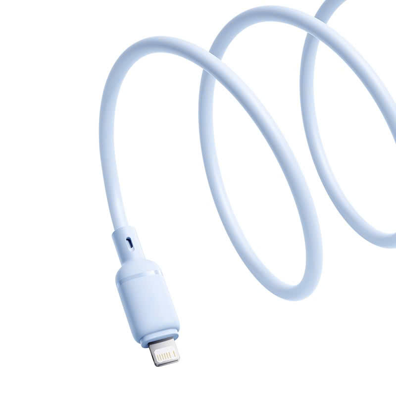
1. Comparison of Lightning and USB-C in Charging Operation
|
|
|
|
|
|
|
|
|
|
|
|
|
|
|
|
|
|
|
|
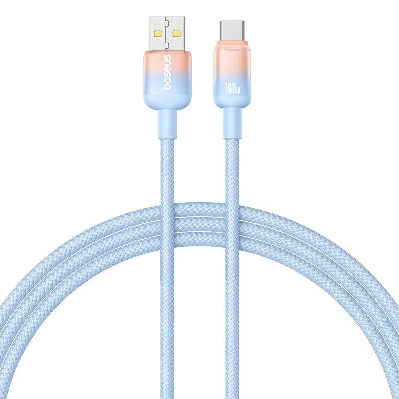
USB-C with more pins (24 pins vs. 8 pins) has more powerful data and power transmission capabilities, supports a wider power range, and has dedicated communication channels to regulate current.
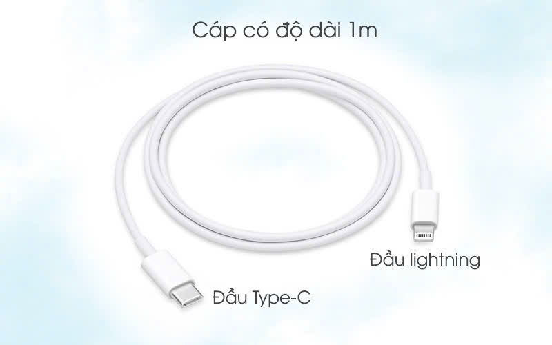
2. The Effect of Wire Length on Charging Efficiency
Here is a basic principle of physics:
- Increase Length = Increase Resistance:The longer the wire, the greater the total resistance on the line.
- Performance Reduction:Increased energy loss(in the form of heat) and Ampere reduction/reality to the device, resulting in charge slower.
- Solution:To maintain fast charging performance at long cables (e.g. 2m), manufacturers must use larger core cross section(thicker copper wire) to minimize resistance.
3. Data Transmission Speed and Core Cross Section
- Data Core:The signal cores (Data and Data-) in the cable are responsible for transmitting data, not electricity.
- Data Transmission Through Signal Core:Data is encoded into voltage pulse and transmits signals at high speeds (e.g., 480 Mbps for USB 2.0, or up to 40 Gbps for Thunderbolt/USB 4 over Type-C).
- Relationship:While power cores need large cross-sections to reduce resistance, signal cores need to be twisted pair and shieldingGood. Larger signal core cross section can also support more stable and high speed data transmission, especially in noisy environment.
Conclude
Apple's strict regulations on charging cable components are not only royalty collection (MFi)but also tight control over user experience and safety.
These standards ensure that products manufactured inPrestigious factory, meeting export standards in Vietnam or anywhere in the world, must fully integrate:smart control chip, overheat/overvoltage protection circuit, and low resistance conductive material to provide 20W+ PD power in the safest and most stable way.
Trusted iPhone Fast Charging Cable Manufacturer in Vietnam